CONSTRUCTION / DROP-STITCH · DWF
A wall, not a beam
This page answers three things: how our construction differs from an ordinary inflatable tent, how it differs from the domes used for sports halls, and why 15 cm of fabric insulates like masonry.
- Wall thickness 15–75 cm
- Wind rating > 8 BFT
- Operating range −45~60 °C
- Mass per m² 8 kg/m²
- U-value 0.5 W/m²·K
- Max span 32 m
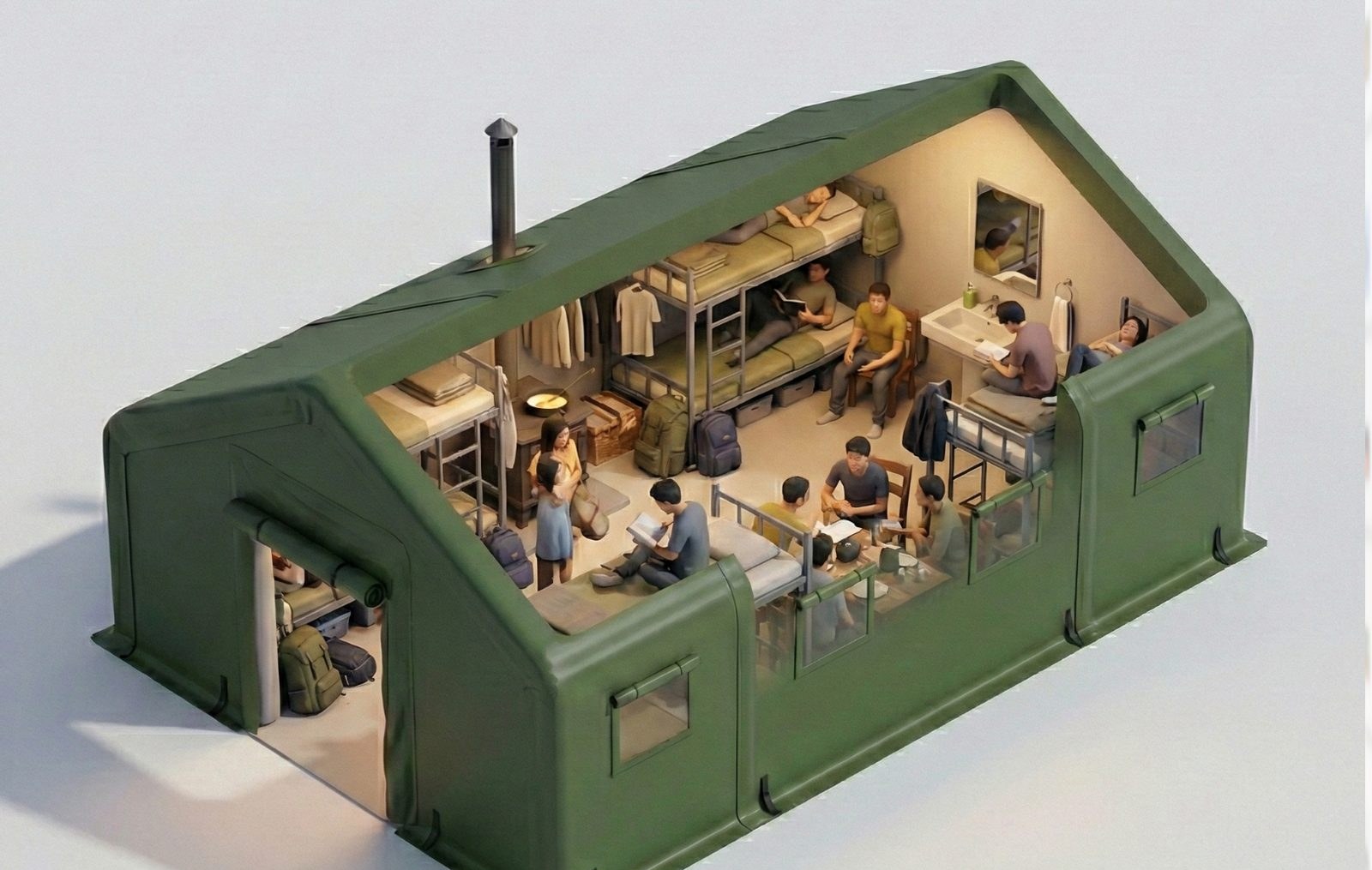
TANDA builds with drop-stitch double-wall fabric (DWF). Tens of thousands of internal threads connect two fabric layers, so that inflation holds the layers parallel and turns each wall into a rigid panel with real thickness, rather than a skin held up on air beams. Wall thickness comes in five grades: 15, 20, 30, 50 and 75 cm. The critical difference from an air-supported dome is that an air-supported structure stands on internal overpressure — the blower must run continuously, the building collapses if it stops, and entry requires an airlock — whereas a drop-stitch structure is self-supporting once brought to working pressure: the air source can be disconnected and people and vehicles pass freely. The membrane cross-section runs blast layer (optional), airtight layer, fabric with drop-stitch threads, airtight layer, blast layer.
"Inflatable building" covers three genuinely different things, and this is where buyers most often get confused.
The first is the air beam: a few inflated tubes acting as a frame, holding up a single skin. Load concentrates in the beams, one deflating takes the structure, and there is essentially no insulation. Most inexpensive inflatable tents are this.
The second is air-supported — the familiar inflatable sports hall or coal store. The whole envelope is held up by internal overpressure, the blower runs twenty-four hours, and people enter through an airlock. Spans can be very large, but cut the power and it comes down, and you cannot simply open a door.
The third is the drop-stitch wall, which is what we build. Tens of thousands of internal threads tie two fabric layers together; inflation pulls them into parallel planes and the wall becomes a rigid panel with thickness. No frame, no internal overpressure holding up the roof. Bring it to pressure and it stands on its own — disconnect the air, open the doors as you like. This is the route Western defense-grade inflatable buildings take.
Membrane cross-section — wall grades 15 / 20 / 30 / 50 / 75 cm
Three inflatable constructions
This is the table to read before selecting anything else. The three types solve different problems and sit in different price bands — choosing the wrong type is a far worse mistake than choosing the wrong size.
| Criterion | Drop-stitch wall (ours) | Air beam | Air-supported |
|---|---|---|---|
| Load path | Whole wall acts as a rigid panel | A few air beams carry load, skin attached | Internal overpressure lifts the envelope |
| Continuous blower | No — self-supporting once inflated | No | Yes — collapses when stopped |
| Personnel and vehicle access | Free | Free | Airlock required |
| Effect of single-point failure | Compartmented; local loss is not total | One beam deflating takes the structure | Breach leads to rapid collapse |
| Wall thickness | 15 – 75 cm | Beam diameter, no cavity | Single membrane, no cavity |
| Insulation | U 0.5 – 0.85 W/m²·K | Essentially none | Requires separate internal lining |
| Typical span | To 32 m single span | Small formats | Very large spans achievable |
| Typical use | Lodging / shelter / hangars / equipment cover | Camping tents, promotional marquees | Sports halls, coal stores, bulk storage |
Air-supported construction still wins on very large spans and cost per square metre. If your project is a fixed-location large venue and continuous blower operation with airlocks is acceptable, that route deserves a comparative quote. We build for the cases that need mobility, self-support and insulation.
Membrane selection
Two membrane systems, differing mainly in low-temperature capability and cost. Getting it wrong usually only shows up in the first winter.
TPU membrane
Markedly better at low temperature, for Central Asia, high altitude, northern winters and cold-weather basing. Flexibility degrades less in cold, and it stands up better to repeated folding and stowage.
PVC membrane
Better on cost, for tropical, subtropical and temperate projects. The low-temperature window is clearly narrower than TPU; not recommended where winter drops below −15 °C.
Deployment sequence
For a 24 m² unit: one or two people, under ten minutes. No lifting equipment and no ground preparation at any stage.
Position and unroll
Stowed as a cylinder. Carried to position, unstrapped and laid flat. No hardstanding and no prior levelling.
Inflate to shape
Connect the air source; walls form automatically into a stable planar structure. Compartmented, with each cell pressurised independently.
Anchor and disconnect
Ground anchors set to the prevailing wind. At working pressure the air source is disconnected and the structure stands on its own.
Deflate and pack
Deflated, folded back to a cylinder, carried and loaded by one person. A 6 × 8 m unit packs to about 1 m³.
On the timing figures
The ten-minute figure is for a 24 m² unit handled by one or two people; a 6 × 8 m unit deploys and strikes in under 15 minutes combined. Wide-span products assemble in modules, so time scales with module count — we state the actual cycle for your dimensions in the proposal.
Performance envelope
Range-wide rated figures. Model-specific values are given on the product page.
| Item | Rating | Note |
|---|---|---|
| Wind rating | > Beaufort 8 | Gusts to Beaufort 10; ground anchoring set to prevailing conditions |
| Operating range | −45 to 60 °C | TPU membrane −41 to 65 °C / PVC membrane −15 to 65 °C |
| Mass per unit area | 8 – 10 kg/m² | By footprint; no metal frame |
| Wall thickness | 15 / 20 / 30 / 50 / 75 cm | Selected by span and use |
| U-value | 0.5 – 0.85 W/m²·K | 0.5–0.64 at 15 cm; above 0.8 on 75 cm wide-span units |
| Roof load (standard) | UDL ≥ 300 kg / point ≥ 100 kg | Accommodation and emergency shelter series |
| Roof load (wide-span) | UDL ≥ 400 kg / point ≥ 150 kg | Large-span hall and equipment cover series |
| Maximum single span | 32 m | Equipment cover series, 180° arc, 13 m clear height |
| On-water deployment | Available | Must be specified at order; buoyancy and anchoring change accordingly |
| Crew to deploy | 1 – 3 people | 1–2 for a 24 m² unit; wide-span by module count |
Page updated 2026-10-10